Build coaxial colinear, circular polarized , corner reflector, and standard gain antennas for 2.4GHz Wifi. A simple 2.4GHz preamplifier build is described. Coaxial colinear antenna design.
Download Excel 2007 workbook, 'Antenna Builder's Companion' to give solutions to every RF related calculation the antenna builder may need
Download Excel 2007 workbook, 'Antenna Builder's Companion' to give solutions to every RF related calculation the antenna builder may need
Basically this design arose from some private research based on curiosity, ie. How small can you make the ground plane, whilst still keeping the antenna in forward-fire mode. The design is now used commercially (ZCG-SCALAR's model CP2400), and is very easy to build. The prototypes used a 50 mm diam. ground-plane, and the antenna was wound with adhesive leadlighter’s foil on a 30 mm PVC or fibreglass tube. The design is automated in the ANTENNA BUILDER'S COMPANION, when tested gave 12 dBd.
The design provides a simple antenna for the point to point wireless LAN use, being fully sealed, and very light as having a minimum wind load. The packet rate is much improved using circular polarisation in these links because multipath reflections have minimal effect.
If building a pair for your own interest, I suggest if you are using ‘foil on PVC’, then design for a frequency 20% high, which the calculator in RF3.XLS does for you. (because of the velocity factor effect, this will bring down the correct response down 20%, to 2400 MHz) If winding with wire, say1mm, design at 10-15% high would be a reasonable starting point. Give a PVC sample 3 min. in the microwave first , and if it barely warms, its ok!
Forget about the ‘first turn close to the groundplane’ advice in the ARRL books., and wind the helical evenly from turn one. Match is accomplished with a ¼” wide tab soldered to ground plane about 1/8 turn around from feedpoint, and standing up beside the winding as illustrated below (determine position with your analyser!)
This match system may not be textbook, but on the Time Domain Reflectometer the response indicates a smooth change of impedance from 50 to the expected 120 ohms by the end of turn four.
A foam "doughnut" at the front held the assembly central in the tube.
Project: 2400 MHz reduced groundplane, circular polarisation antenna, suit point-to-point data, or WiFi.


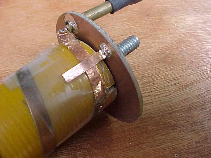
Upper Left: The rough initial concept prototype, bare wind on fibreglass tube. Later pvc tubing was wound with1mm wire.
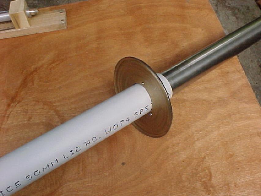
Upper right: Ground plane sits against mouth of SS mount tube. Reduced groundplane is exact diameter of the mount tube.
Lower Left: Tab match gives a smooth impedance transformation, despite not being "textbook" My suggestion to those without an analyser is to use the stub at the length shown with a right angle foot for soldering, and slide it around for maximum signal on your wi-fi card's RSSI before soldering it in the final position. Tab position is fussy, and if you do not get it right, you will be disappointed in the build.
Lower right: After the antenna is assembled, a metal ring can be slid over the PVC tube and locked in position as if it was continuous with the internal, reduced groundplane. Although no electrical continuity exists, the gain of this setup is very close to the traditional design, with a single continuous groundplane. This external ring is optional.
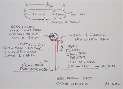
Project: DIY WiFi, 2.4 GHz corner reflector. A simple to build, excellent performer.
Gain was measured as slightly better than my Standard Gain 2.4 GHz antenna.
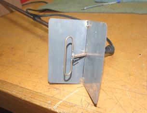
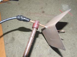
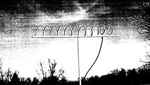
My initial inspiration for this design. Kraus, pioneer of the Helical published work on a helical with groundplane replaced by a loop, this 10 turn model achieving 15 dBi.
IEEE Antennas and Propagation, Vol 32, No.2. 2 April 1995, P45
IEEE Antennas and Propagation, Vol 32, No.2. 2 April 1995, P45
Project: Skirted Dipole for 2.4 GHz
The skirted dipole is an easy to reproduce antenna, even if a little tedious to build, and this version uses the slug match and desigh notes in ANTENNA BUILDER'S COMPANION. The core of the low loss RG58 is passed through the 5mm tubes to which the elements are soldered.
Project: Standard Gain antenna, 2.4 GHz, but very suitable for WiFi.
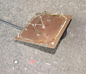
Design dimensions are per a calculator on worksheet in ANTENNA BUILDER'S COMPANION
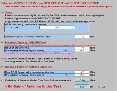
Easy to build. Glue a standard strawberry punnet (removed for picture) over the delicate elements for protection. The benefit of this design is that the matching is simple and the gain is certain. Using the RSSI on your wireless link, prize apart or squeeze the split balun for maximum signal, assisted by worksheet "ANTENNA GAIN per RSSI". .
Easy to build. Glue a standard strawberry punnet (removed for picture) over the delicate elements for protection. The benefit of this design is that the matching is simple and the gain is certain. Using the RSSI on your wireless link, prize apart or squeeze the split balun for maximum signal, assisted by worksheet "ANTENNA GAIN per RSSI". .
Project: DIY directional coupler
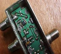
Built from ferrite cores found in low cost TV couplers or taps as in illustration on right, and very handy for your antenna matching..The ferrite coupler has to be removed with tweezers, and with great care. I have hand wound couplers on suitable TV balun cores, but was never able to equal these commercial miniatures at the higher frequencies.
.
.
Project: Using receiver RSSI for instrumentation
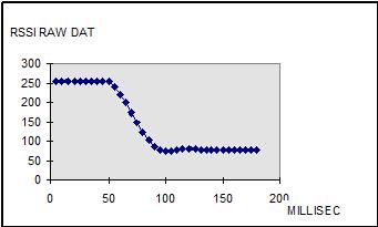
Placement of stubs needs the measurements of line voltages. Use your existing RSSI, but there are things like settling time, graphed on left for a Winradio card, that may trip you up if quickly stepping through values.
(An obsolete project, how we have nanoVNA!)
(An obsolete project, how we have nanoVNA!)
Project: DIY Slotted line
A knowledge of your load reactance is essential to allow accurate stub calculations. It's very easy to build your own slotted line, and when used with your reciever RSSI and the ANTENNA BUILDER'S COMPANION, you will be able to match your antenna perfectly.
(Legacy project, ,nanoVNA now preferred!)
(Legacy project, ,nanoVNA now preferred!)
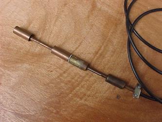
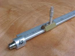
Project: DIY Slotted line 2, and modernising the HP805 slotted line
DOS program source code in C, to automate all measurements on home made slotted lines, or a modified HP805 line. OBSOLETE, but handy for those who need math or code for impedance measurements.
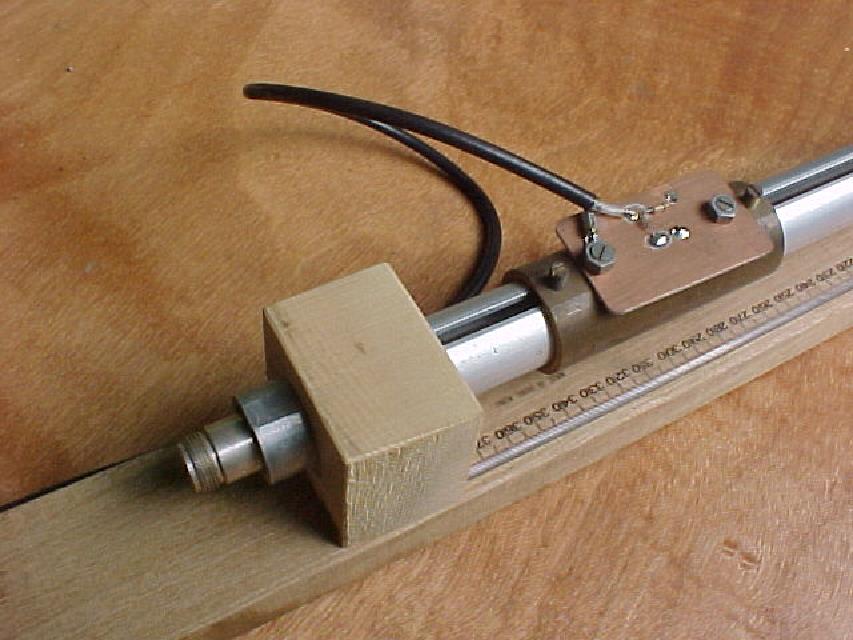
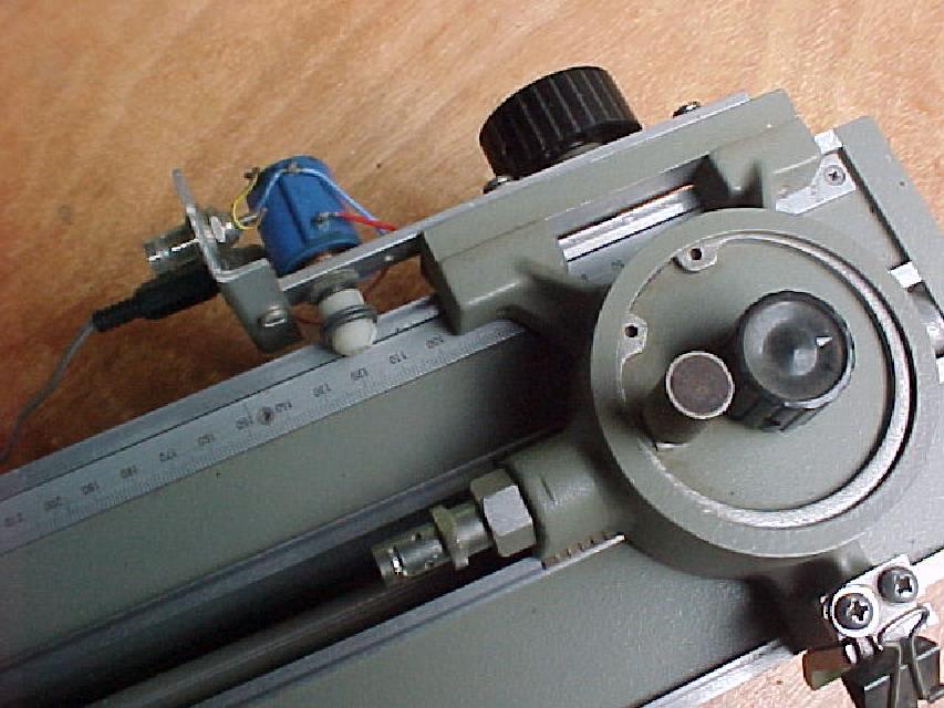
The HP805 has a ten turn pot mounted on the carriage (see below), and the rubber wheel runs along the top of the bridge to give accurate position measurements. The software gives a graphical display of reference and load traces, and analyses automatically after cursors are moved to the max and mins. If thinking of compiling this, you will need the SMPLUS library, link is on Arduino pages, as is a sample trace from this program (Legacy project, ,nanoVNA now preferred!)
The HP805 has a ten turn pot mounted on the carriage (see below), and the rubber wheel runs along the top of the bridge to give accurate position measurements. The software gives a graphical display of reference and load traces, and analyses automatically after cursors are moved to the max and mins. If thinking of compiling this, you will need the SMPLUS library, link is on Arduino pages, as is a sample trace from this program (Legacy project, ,nanoVNA now preferred!)
Project: Scalar Analyser OBSOLETE, but handy for those who need math or code for impedance measurements.
"scalar.c", program source code in C, gave two options for a Scalar Analyser.
First used a bridge, fed by a SMS signal generator stepped through a selected frequency range. The Icom R7000 was stepped to match and the RSSI used to do the computes. Of course, sweeps with shorts and opens were required first, but gave very good results.
Second mode used a different technique. A HP 8690B Sweeper is set up to sweep relatively slowly. The frequency is read regularly during the sweep via the serial output of an Optoelectronics 8048, and the dual directional coupler provides fwd and ref at each step via calibrated HP detectors with 100K loads. This setup is illustrated below.
This gave amazingly good results, and replicated the boss' Wiltron 54100A sweeps. He must of wept, because it had cost him an arm and a leg. (Legacy project, ,nanoVNA now preferred!)

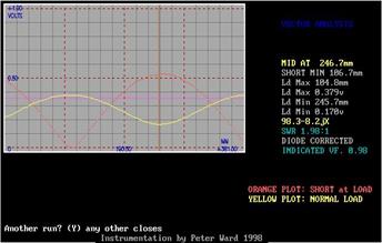
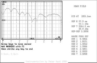
Left: SLOTTED.C also had ability to display a near field track. Antenna was mounted on wooden frame, and probe with 10 turn pot and wheel gave position data. Antenna tracked above was first look at a sleeved colinear that was not phased!
Project: Smith Chart
DOS program source code in C, investigating drawing a Smith chart. May be useful graphical code.
Folder also contans some functions in C useful in antenna design
Folder also contans some functions in C useful in antenna design
Cheap and easy slotted line, if you can machine or "dremel" the slot without disaster!
Project: Alternative feed and match for 2.4 GHz and 5 GHz WiFi yagis
Presented pictorially, a picture worth a thousand words. An analyser is the ideal tool, but these can be matched effectively by reading below.
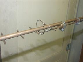
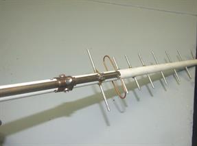
Lambda loop yagi feed (one wavelength in diam.) with a split sheath feed.
Loop, as in Corner Reflector project above. Split sheath is tuned by sliding a short along split, soldering in final position.
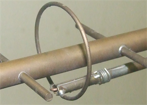
Lambda loop feed, close up. Instead of a tab, as in the Corner Reflector project, a short is slid along the feed until match is correct, and split can be pinched or opened to assist in finding optimal match. In the absence of an analyser, you could tune for maximum signal on your wi-fi card's RSSI. The chips used to measure RSSI are highly accurate, and could be used for antenna gain comparison. If doing such comparison, calculate cable losses for each antenna, especially if your antennas have pre-attached cables, many of which are of dubious quality and have huge losses at 2.4GHz
Project: Smith Chart
DOS program source code in C, investigating drawing a Smith chart. May be useful graphical code.
Folder also contans some functions in C useful in antenna design
Folder also contans some functions in C useful in antenna design
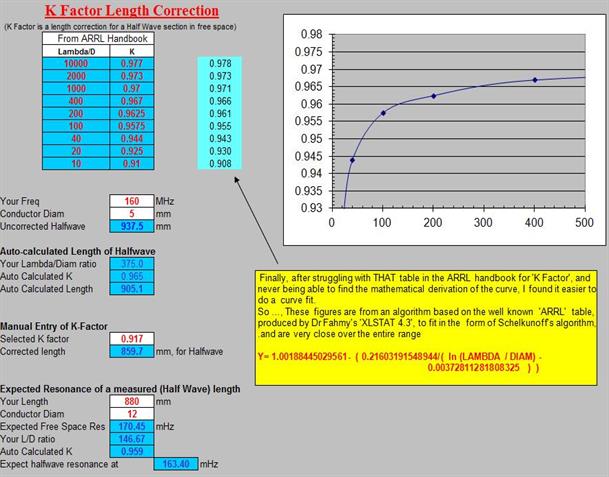
Project: K-Factor. Some useful understandings for antenna builders
Every antenna element needs shortening from its calculated (theoretical) length.
You can use the tables, such as in the ARRL handbooks, or use the formula in this short note
You can use the tables, such as in the ARRL handbooks, or use the formula in this short note
Achieving a good VSWR is our aim in all antenna projects. Too many boast about their achievements, without any knowledge of the uncertainties involved. Read this, and download Rf2.xls (RF page) and you will be able to calculate your worst case uncertainty. (Since writing this note, I think Anritsu have adopted a RSS method in their later publications. This does not negate the need to understand what your actual uncertainties could possibly be) Now incorporated into ANTENNA BUILDER'S COMPANION, preferred download above
Matching at UHF and above is always tricky, but I have found the slug-match the easiest of all. Download Rf2.xls. Sheet 11 will help you calculate slug section sizes, but you need to know feed point impedences first, unless you are happy to do a lot of trial and error only using tyour RSSI indicator for max gain..
Coaxial gain antennas, and crossed cable section gain antennas are poorly understood. Download these notes and build them correctly. Whilst crossed cablesection antennas can be easily built for 400-900 MHz antennas, in practice I have not had success in a commercial design at 2.4GHz, probably because of effects at the crossover joints that are not understood, and because of dimensions and matching being so critical. Actually, difficult enough at 477 MHz, and I have seen an entire production run trashed because of a slight cable VF variation.
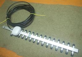
This yagi should be an ideal for 2.4 GHz. Looks great, but this one disappointed, just over 4 dBd. Tested four, all just as bad!
DIY hint:- First quality low-loss cable is essential. Buy top brand cable and connectors, and observe "minimum bend radius", Your normal RG58 cable will not do here.
If testing on your analyser, test with any element end caps on. Adding them after testing will surely throw the resonance point off.
DIY hint:- First quality low-loss cable is essential. Buy top brand cable and connectors, and observe "minimum bend radius", Your normal RG58 cable will not do here.
If testing on your analyser, test with any element end caps on. Adding them after testing will surely throw the resonance point off.
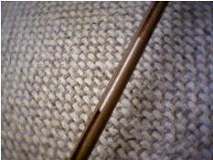
This feed for a 2.4GHz coaxial colinear has the feed made of a RG58 Low Loss cable inner fed up a brass tube. A section of dielectric is removed , and a slot cut so the "slug" can be moved to effect the match.
BUYER BEWARE!

Download Rf3.xls, on my RF page. Sheet 1 will help you calculate design dimensions for a crossed cable section antenna, as illustrated below. Further down this page is a download, 'EASY SMITH' that has suggestions/ diagrams of matching techniques that would apply to this design also. Now incorporated into ANTENNA BUILDER'S COMPANION, preferred download above
Now incorporated into ANTENNA BUILDER'S COMPANION, preferred download above
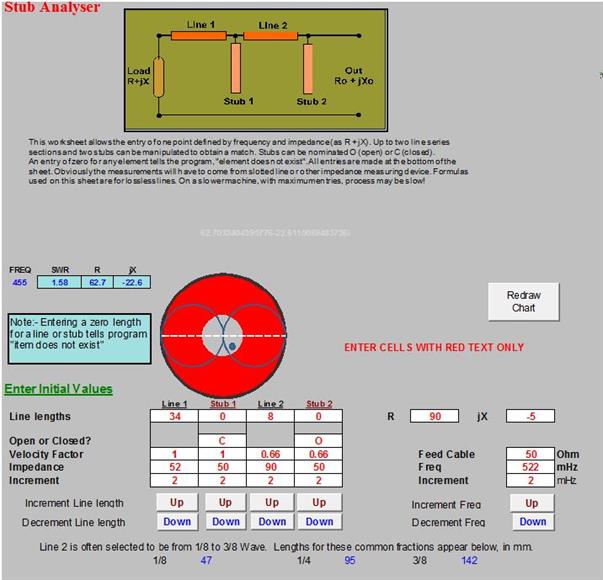
EASY SMITH shows how to match a known impedance on the SMITH CHART, following simple rules that are clearly explained, even if you do not fully understand the science behind its use. Unfortunately you still need to know your feed point impedance before you can use this aid.
You need to read this info, and use the referenced worksheets in Rf2.xlsm, available on the Excel pages. Now incorporated into ANTENNA BUILDER'S COMPANION, preferred download above
You need to read this info, and use the referenced worksheets in Rf2.xlsm, available on the Excel pages. Now incorporated into ANTENNA BUILDER'S COMPANION, preferred download above
Project: Simple guaranteed gain, easy to build UHF amplifiers.
Using the MAR-2 chips is so simple in this design. A 'Dremel' grinds away the tinned outer cable to expose the core, which is split for insertion of the amplifier. Design is from Worksheet 11 of RF4.xlsm Now incorporated into ANTENNA BUILDER'S COMPANION, preferred download above
These are great for both instrumentation, and weak signal boosting on the antenna range. Being 'one way' are not for Wi Fi boosting.
These are great for both instrumentation, and weak signal boosting on the antenna range. Being 'one way' are not for Wi Fi boosting.
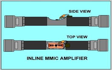
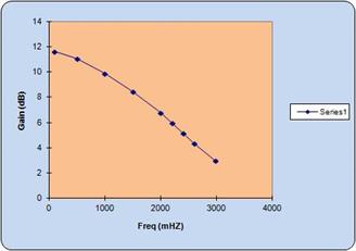
Where you need a tuned amplifier, a MMIC can feed a simple resonant section can be, constructed as follows.
Copper strip, 3.25mm wide x 0.25mm thick, from a leadlight craft supplier, is formed so underside of strip is 5.5mm above groundplane. A small copper disk can be used to lower resonance frequency, also can be slid slightly each way to obtain tune/match prior soldering. Input and output taps will be 1 - 3 mm from end. The charts below arise from building circuits for signal sources as discussed in 'VHF UHF Manual', Jessup 1987, Sect 9.10, 9.21, and have been used to build amplifier chains. Using 0 -10 pf capacitor at center ( between strip and earth) instead of disk lowers resonance, and also allows a better range of adjustment.
Copper strip, 3.25mm wide x 0.25mm thick, from a leadlight craft supplier, is formed so underside of strip is 5.5mm above groundplane. A small copper disk can be used to lower resonance frequency, also can be slid slightly each way to obtain tune/match prior soldering. Input and output taps will be 1 - 3 mm from end. The charts below arise from building circuits for signal sources as discussed in 'VHF UHF Manual', Jessup 1987, Sect 9.10, 9.21, and have been used to build amplifier chains. Using 0 -10 pf capacitor at center ( between strip and earth) instead of disk lowers resonance, and also allows a better range of adjustment.

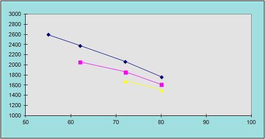
STRIP LENGTH
FREQ
Project: Simple copper strip inductors for UHF amplifiers.
Side entry UHF socket is used to feed in the 12v supply for the amplifier
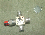
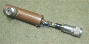
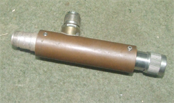
This version uses a slug match. It has also been commercially produced using a small, hairpin loop as a closed stub, but the placement is critical and 1.5mm too far forward or back makes the antenna impossible to match. The slug match is by far the easiest to implement, but needs a steady hand with the 'Dremel'
By request of my then employer, I tried unsuccessfully to incorporate extra dipole sections, but despite a lot of work was not able to succeed with phasing it correctly. Basically, the pattern and gain was a long way from what I predicted.
By request of my then employer, I tried unsuccessfully to incorporate extra dipole sections, but despite a lot of work was not able to succeed with phasing it correctly. Basically, the pattern and gain was a long way from what I predicted.
Coaxial design notes. Now with dimensions for this antenna, as extracted from my lab notes.
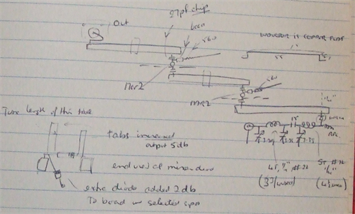
A practical application of these strip resonators was a 2.4GHz signal source, with two stages of MAR-2 amplification, from my lab notes. Interesting to note that the simple addition of two small tabs to the diode multiplier increased the final output by 5dB. Such is RF!
Project: Coaxial Gain Antennas
Including designs for DIY WiFi antennas, based on my experience with both designing, matching, and troubleshooting them at the production level.
UPDATES: 30 Jan 2020 Added ESP8266 RSSI project, plus advice for 2.4 gHz DIY antenna builders
17 Jun 2020 The old XLNEC antenna modeling program just rebuilt, released as XLNEC-2. Many new features, improvements, bugfixes,
moved to an 'xlsm' platform, verified in Win 10. NOW MOVED OVER on the RF TAB
9 Aug 2020 $50 DIY Antenna patterning range for WiFi
\
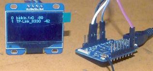
ESP8266 RSSI project. For 2.4 GHz antenna builders without test equipment! About US $16
Without specialised equiptment it is difficult to optimise a DIY antenna build for 2.4 GHz IOT use, but it is possible to use an ESP8266 RSSI (received signal strength indicator) and optimise the build by ‘fiddling’, aiming for the best signal strength (dBm reading)
Such a method does not prove an optimised antenna, only that the maximum signal has been picked up by the antenna / lead combination at that mount location and lead position.
Also, RSSI is very useful for optimising antenna placement for your IOT fixtures.
Being easy to setup, an ESP8266 coded to provide its RSSI is a cheap and simple aid for your tool box.
I use a WEMOS MINI PRO, the variety provided with an IPEX connector, IPEX to SMA patch cord, and a useful 2.4 GHz antenna, and costing only US $8. You must unsolder the link from the on board ceramic antenna, and replace in the alternative position, to join the IPEX connector. The ‘Zero Ohm’ (just a fancy name for a shorting link) resistor is difficult to re-solder, and can be replaced by a piece of fine wire.
Display screen is a 1.3" SH1106 128X64 OLED LCD LED Display, currently about US $8
Simple advice for a non technical builder using RSSI as their only piece of test equipment.
* Every 3 dBm improvement in RSSI represents a doubling of signal strength.
* Antenna resonant lengths are determined mathematically at any given frequency. The skill is matching the antenna impedance at the feed point (where the feed cable connects)
* Without test equipment, stick to a proven design, only fiddle with match (position of matching tabs, length of matching stubs) Never change the design length or diameter of radiating elements.
* Relative element spacing in multi element designs is mathematically determined (modeled) and should not be changed.
* Signal loss can be huge in feed cables. Low loss suitable for 2.4 GHz are needed varieties are needed. Likewise, signal loss can be huge in poorly assembled connectors. For the non -technical, buy pre assembled patch cables.
*Feed cables that are kinked, squashed, or bent at less than minimum curve radius will also lose signal
RSSI will vary with antenna position. Because of interaction of reflected signals, there are both places of signal enhancement, and of cancellation. Such variations are caused by both fixed, and moving objects in and around the signal path. You can mount antenna to use a point of enhancement to advantage, but ensure it is a stable reflection. High mounted antennas as far as possible without moving objects in signal path is preferable.
Antenna element design lengths, and cable loss comparisons are easy to calculate in spreadsheet herewith, RF1.XLSM
Extract from 'Antenna Builder's Companion'. Read it twice! You can waste a lot of time on this design, and still end up disappointed.
2.4 Ghz "cable and Sleeve" Coaxial Colinear Antenna
The mystery antenna of “Estqwerty's DigDice diy wifi antennas" ( Illustrated above per DigDice website photo
http://www.digdice.com/category/antenna/omni/page/4 ) actually is NO MYSTERY
An antenna that looks so simple, but one very hard to "tame".
This design is common, having been sold for many years, and I have reverse engineered both the ZCG-Scalar Z-150, and Antenna Engineering's HU6.
Both companies advertised the antennas as 6dBd and the patterns show an expected down tilt. (I cannot guarantee the HU6 design is still as the one I dissected, and the Z150 is discontinued.)
Tasked to scale this antenna to 2.4 GHz and reduce pattern down tilt to a minimum, I was given an unlimited time budget, good test equipment, antenna range and a near field probe on a wooden track. My lab diary records ninety six models built and tested in the format illustrated below.
Basically, when I dismantled these antennas, they consisted of repeating bare coax center cable radiating sections, with tubing as cable “suppressors” (at least that's what the original design engineers called them on the blueprints)

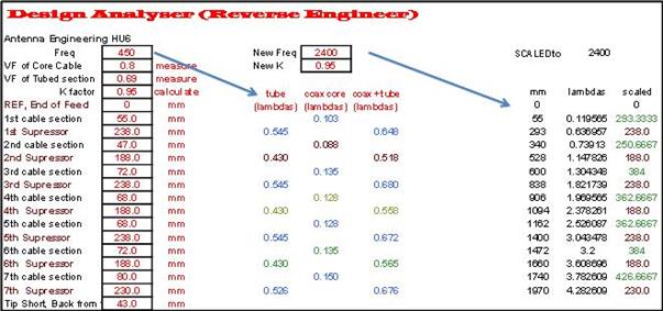
Below:- The start of my efforts was a reverse engineering of both antennas in an attempt to understand the significance of each build dimension. Antennas were measured, analysed on a spreadsheet (below, or download RF3.xls) and used as a starting point for 2.4 GHz models. Each model had to be built, matched, electrical center found, and the pattern analyzed.
Before the exercise was over, a total of ninety six models had been built, as the bench diary shows!
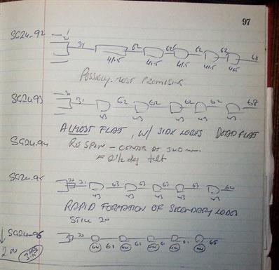
YES, 96 builds!

After more than a week's work, what can I tell you?
1. You can achieve 6dBd with about 3 or 4 degrees downtilt. Attempting to decrease to less than that results in a very touchy build, pattern break up, “butterfly wings.” A 'flat' pattern is impossible in an antenna which is fed from the base. Five sleeves are manageable, more gave no advantage.
2. Matching is easiest by a slug on wire in base tube.
3. Dimensions are critical. Sub millimeter accuracy in cutting and placement is needed.
4. Using RG213 inner, start with the dimensions shown as Build 92 above. Work with tubing element lengths of 40 to 41.5mm. I used tight fitting aluminium sleeves over RG213 inner.
Of all my 2.4 GHz antennas, this is the easiest to build and match, as well as being a guaranteed performer. Dipole is the critical element do not vary its dimensions. Match can be 'assisted' if neccesary by sliding the assembly forward or back on the reflector before soldering (ensure it is a tight fit)
A FINAL WORD for those working in the DIY environment.
My hard earned advice is firstly, that whilst it is easy to build a neat looking antenna, unless you include a design feature allowing adjustment to your matching, even on PCB based designs, you may end up with a lot less signal than the design suggests.
Secondly, without the right test equipment, it is almost impossible to verify phasing of elements on multi-element antennas. As soon as you get past the first couple of sections, you may find adding the next section has a big effect on the phasing and matchings of the sections you have already tested and are happy with.
Thirdly, unless you decouple the line correctly, your pattern will never be what you expect.
Many published DIY designs are based on scalings from lower frequencies. Direct scaling, although theoretically possible, generally is not successful if scaling from HF to microwave frequencies. Choose to build designs that have been proved on the range!
Arduino code for ESP8266 RSSI
Excel workbook for calculating basic antenna dimensions, and cable losses
This project uses WEMOS MINI PRO, which has an IPEX connector allowing you to connect an external antenna via pigtail.
Project: Simple 2.4GHz ANTENNA PATTERNING RANGE for the DIY WiFi antenna builder.


The D1 Mini Pro was chosen because it has an IPEX socket for connection of an external antenna.When rotation completes, pattern is re-plotted, normalised against strongest RSSI returned, and presented as a standard ARRL style radiation map.
You will have to understand the limitations of a home antenna range, observe minimum (three lambda) separations, do your best to avoid multipath reflections.
Do not expect to pattern correctly in your kitchen! Suggest you put a directional antenna on your WiFi access, and move it temporarily outdoors!! Best to implement a 'slant range' . Not easy, but much better results.
Also, you must swing about 'electrical center.' Skewed patterns will result if for example a yagi is swung from its normal end mount.
How do you find 'electrical center? Observe current strength and distribution on your modelling program.
Next best is a fudge. If your pattern is not looking like the modelled antenna, shift antenna about until it best resembles!
If doing gain measurements against a standard antenna, ensure antenna is matched to line before connecting! Remember, max power transfer applies just as much to forward power from TX, as it does to power transferred from antenna.
You will need some high quality connection cables, and possibly adapters. The antenna mount must be non-conducting, and I have used the riser from a garden irrigation sprinkler, slightly opened to 5.3mm at base for a very tight press fit to the stepper.
It will not be possible to determine absolute gain figures unless you build a standard reference antenna (not hard), but you will then easily refine designs and roughly quantify improvements
Total investment will be about $50,USD and the build can remain on the protoboard.
Purchase list:- MB102 Protoboard and power head.
24BYJ-48 stepper and ULN2003 driver
Lolin D1 Mini Pro
1.8" 128x160 TFT, ST7735 driver
2x18650 cells, plus holder and plug to suit
Cable to connect from IPEX to antenna. Normally IPEX connects to a REV SMA, which connects to antenna base. You may need to extend this to allow antenna to rotate.
Accompanying Arduino code, “ANTENNA_PATTERN_STANDALONE_128x160_V2.ino”, can be uploaded to the D1 Mini Pro via Arduino IDE, which needs a little setting up for the ESP8266 processors. This is well covered on available internet notes.Those that want more torque from the 24BYJ-48 stepper can do an easy mod, which will convert it to a normal bi-polar stepper, driven thru your choice of step/dir driver. I have found the standard 24BYJ-48 totally adequate to spin any 2.4 GHz antenna. This is a very basic project, but when used together with a nanoVNA V2 to check match, should give useful characterisation of your DIY WiFi antenna. Those wanting something more comprehensive, should read next, and download the ANTENNA BUILDER'S TOOLBOX over on the RF page
Left:
Using the RSSI return from a D1 Mini Pro, this program swings the antenna through 360 degrees, plotting every two degrees (or as you choose). Rotation is achieved on a 24BYJ-48 geared stepper. Signal source is your own WiFi router.
Using the RSSI return from a D1 Mini Pro, this program swings the antenna through 360 degrees, plotting every two degrees (or as you choose). Rotation is achieved on a 24BYJ-48 geared stepper. Signal source is your own WiFi router.

Above: For those needing a full featured antenna range, this 'big brother' to the WiFi range is over on the RF page, in the ANTENNA BUILDER'S TOOLBOX. The program for this range is supported by integrated software to smooth and print the pattern taken from the file stored on SD. This design can be scaled for a full sized antenna rotator, uses normal 200 step stepper.
. 'ANTENNA BUILDER'S COMPANION.xlsm' A large EXCEL workbookfor antenna builders, containing pages to calculate everything you will ever need in building and matching antennas. Plenty of practical help in principles and implementation. A recompilation and updating of all antenna related material from my earlier RF1, RF2, RF3, RF4 'RF' workbooks. A lot of material will help nanoVNA users.
Verified on Excel 2007 / Windows 10. NOTHING in this workbook is locked, so you can check macros for yourself
Verified on Excel 2007 / Windows 10. NOTHING in this workbook is locked, so you can check macros for yourself
Above: Kitchen table antenna pattern is rough but useable
2.4 GHz corner reflector antenna, rear.
2.4 GHz corner reflector antenna, front
Left: Feed construction for the 2.4 GHz corner reflector
Above. Interactive impedance display in Excel workbook, 'Antenna Builder's Companion'
Above: ZCG-Scalar Z-150, Antenna Engineering HU6, and DigDice all had alternate radiator and supressor sections. All have downtilt, but are useful designs
Above: DIY 2.4 GHz skirted dipole is similar to commercial offerings, but uses an unique matching system.
Above: DIY 2.4 GHz standard gain antenna
Above: Design page forDIY 2.4 GHz standard gain antenna