Hints and modifications to get the best results from a Geetech i3 Acrylic Pro B kit.
Learn from my experience assembling GEETECH i3 Acrylic Pro B Kit, ”tips”, and a quick, reversible Bowden modification for this 3D printer. Although written a few years ago, the hints and modifications may help anyone using this class of 3D printer
In summary!
If you are a non technical person, you have big challenges in completing the assembly, then adjusting, modifying and calibrating to get quality, artifact free, results.
Do not expect factory ‘configuration.h’ files to be perfect. You will need to fine tune settings before you get good results. In particular, acceleration and jerk settings are by many considered to need changes. Steps per mm for X/Y axis were slightly ‘off’ in supplied config file. I assume slight ‘off tolerance’ on drive rollers caused the corrections needed.
You will find this otherwise excellent kit is let down by several poor quality components. The Mk8 extruder supplied with my kit had several ‘out of the box’ faults preventing print completion. Rods were rough and bent.
Sorting out the addition of a BLTouch probe, which I believe essential, will test even the most technically minded!
The design of this, and similar printers, with high reciprocating masses and a relatively lightweight frame, makes high speed printing without vibration artifacts almost impossible without modification. With modification, and a lot of learning, excellent prints should be possible.
The GEETECH instruction manual contains errors, some of which were flagged as early as 2016.
1. Position of locking collars is shown as outside ‘X’ carriage ends. WRONG! Must be inside, or a tensioned belt will pull
carriage ends toward each other, causing binding.
1. Position of locking collars is shown as outside ‘X’ carriage ends. WRONG! Must be inside, or a tensioned belt will pull
carriage ends toward each other, causing binding.


Assembly instructions incorrectly show collars on outside of ‘X’ carriage
Collar must be to inside, or a tensioned belt will pull carriage ends toward each other, causing binding.
2. No mention is made of putting washers on 3 mm bolts. They are supplied, and needed under both nuts and bolt heads to spread load forces on acrylic.
3. Manual documents some incorrect 3mm bolt lengths, eg., for Z axis stop.
4. Not mentioned, but essential. As the Z axis motors are in parallel, Z axis driver board will need the current adjusted to double that used for a single motor. To avoid ‘Z’ motor stalls, I am using a pot setting of 1.1v, up from the default approx 0.7v, on the A4988 drivers. Despite advice on the blogs, I find no need to “upgrade” from A4988’s.
5. Not mentioned in the build notes, is that flex couplers should have minimum T8 / driveshaft insertion, ideally not past the closest portion of the “cut.”
Some essential modifications will be needed. Not all offerings are useful.
1. Top end of Z axis should be free floating to reduce the chance of carriage binding. Open the 8mm hole to at least 9mm, and be careful not to crack the acrylic. Do not add ‘Thingiverse’ add-ons that constrain the top end of the T8 rod in a bearing!
1. Top end of Z axis should be free floating to reduce the chance of carriage binding. Open the 8mm hole to at least 9mm, and be careful not to crack the acrylic. Do not add ‘Thingiverse’ add-ons that constrain the top end of the T8 rod in a bearing!
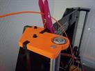
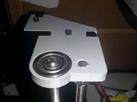
https://www.thingiverse.com/make:265333
https://www.thingiverse.com/thing:1776244
Neat add-ons from Thingiverse, but marginal motor power and slightly bent T8 rods may make binding an even greater problem with upper end tightly constrained. The T8 rods move the carriages, have no job in positioning, and can safely float free at the top to help prevent binding.
2. Per my experience, and other reports, most chrome carriage rods will need straightening before use. Also, as the chrome plating has been made directly on steel, it is rough in places. You may choose to source better quality “hardened and ground” rods.
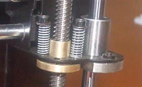
3. Z axis drive nuts will benefit some ability, per following modification, to move slightly to reduce motor stalls due to binding.
My ‘X’ Carriage drive nut cure for binding. ‘Soft lift,’ a modification requiring no disassembly.
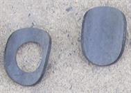
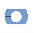
Soft washer goes between the i3 ‘X’ carriage and lift nut.
Old bicycle tube provides suitable material for the cushion washer.
Final washer shape, trimmed and split to allow installation to i3 ‘X’ carriage lift nuts without full disassembly.
Using hole punches, soft washers were prepared from an old bicycle tube, trimmed and split.
The hole in the carriage plate was opened fractionally with a file, so the brass boss could just ‘wiggle’ freely.
Washers go between boss and mount plate. Spring loaded screws hold the boss very lightly to the plate. The tiny bit of freedom so obtained stopped all binding. As the 8mm chromed rods are responsible for positioning the carriage, this mod causes no loss of accuracy. Light duty springs can be taken from an old retracting pen.
4. Bulldog clips on front edge of glass build plate will inevitably cause collisions, especially if an out front BLTouch probe is use. A simple low profile clip cut from an A4 binder edging (shown) is better.


BLTouch probe will at sometime catch bulldog clip.
Replace bulldog clips with section cut from A4 plastic binder edge strip.
5. A layer of lightweight insulation is needed to minimise heat loss from underside of bed. High tech pads, probably the same material as used in kilns are available, but I used corrugated cardboard with a felt sealing ring around the outside.
6. A marker on each flexible Z axis coupler is essential, to quickly show if steps have been lost.
7. Belt roller holders will need filing to accept roller carrier. The forming process had distorted mine to the point they were binding in the frame.
8. If you receive an over-size 8mm rod, as I did (one rod 8.12mm, others 7.98mm), you will need to carefully file the X frame end holes. Others have recorded this problem.
9. Anti vibration bed for entire printer. My solution was to lay thick non slip 1.5mm rubberised anti-slip cloth over a 19mm piece of MDF on which the printer sits.
10. Speeds and accelerations as defaults in Marlin are too high for this frame and motor power, will need resetting.
11. Constant changes of direction whilst printing loosen motor fixings. In particular, use Loctite on motor drive grub screws, and flex couplings. The allen key with my kit was soft and useless. Get a quality key and really tighten those grub screws.
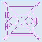
12. A lightweight, three bearing bed whose DXF file is easily found, plus my ‘quick change’ Bowden modification, may be a path to faster printing.
You have to live with unfixable design limitations.
a. At home on my machine , nozzle is 10 mm (X) to left of build area, but 6mm (Y) over plate, thus restricting model ‘Y’ dimension to 194mm.
b. 8mm carriage guide rods could be considered lightweight.
c. The 8mm acrylic bed, together with insulation, heater, and glass is heavy. Heavy reciprocating masses on a lightweight frame with 8mm guide rods makes vibration-free finishes difficult, unless accelerations are kept low.
DXF’s for a lightweight i3 bed are freely available,
but sharp corners and narrow load bearing arms of this design suggest a rework may be desirable.
If re-engineering this file, I suggest:-
1. Remove cross braces.
2. Thicken arms slightly.
3. Round all angles for better stress distribution.
but sharp corners and narrow load bearing arms of this design suggest a rework may be desirable.
If re-engineering this file, I suggest:-
1. Remove cross braces.
2. Thicken arms slightly.
3. Round all angles for better stress distribution.
d. No adjustment to filament drive roller pressure is possible on the plastic lever extruder supplied. The spring appears excessively strong, and may account for lever and bearing center pin failures.
Operating steppers in 1/16 step mode greatly reduces available torque, so in trying to overcome motor stalling on original filament feed, I changed to 1/8 step, before finding the cause to be a faulty pressure roller bearing.
Being lazy, I left my extruder (now converted to Bowden) running 1/8 step mode, with no obvious artifacts on prints. This mode may introduce artifacts with original direct drive, but the Bowden tube introduces a springiness that seems to fully smooth the feed. (Endless, futile speculation exists on step mode and torque. Go to any manfacturer’s site to confirm this fact)
Do not try 1/8 step mode on motors feeding T8-4 start threads.
e. The Z axis steppers are connected to the driver in parallel. Not a recommended method. They may move out of synch at turn-on. Depending on where the rotor was at switch-off, it will jump to an equilibrum position, probably coinciding with a full step position. One motor may jump one way, the other may go the opposite if one has lost steps and the other hasn’t during prior operation. Be prepared to constantly review the end heights of the X carriage. You will have to check this at every print until you no longer have binding or missing steps. Opening the top plate hole for the T8 rod, and giving the drive nut a small amount of freedom per my mod, and setting the driver current appropriately has fixed all my missing step woes.
6. A dust cover is not provided, essential. Once you have oiled the T8 screws and guide bars, dust will stick. The Z axis has no power to spare for driving dirty screws.
Things that you may need to know or attend to!
1. Default settings of steps per mm in ‘configuration.h’ were not exact for my printer. You will have to calibrate X, Y, and Z and either re-compile Marlin and upload (Requires you to be familiar with Arduino IDE), or use M92 commands and save with a M500.
2. If running G code files from SD card, you must disconnect your USB cable from your computer. Leaving it in place on a Windows machine results in random re-boots of Marlin, resulting in crashed prints.
3. If using someone else’s configuration file when setting up BLTouch, take care. I found a mixture of table coordinate systems used in several example offerings available for download. See later notes re. coordinate systems.
Geeetech Power Supply. Immediate smoke.
My power supply failed several minutes into my first attempt to print. I have replaced it with a 350 watt model, as offered standard in some i3 clones, together with an uninterruptable, stabilizing, power supply. (Add another AUD200 to the it price!)
Note, buying a higher wattage supply will not help with what I believe to be the problem that destroyed mine, but fixes the oft mentioned problem of low voltage found with 160 watt models.
I believe a particularly Australian problem destroyed mine.This comment may not apply to your service area.
To explain:-
All Chinese power supplies are rated at 220v. In Australia, we now have 230v standard, but earlier had a 240v standard, which many Australian states still use. Those of us still with a street transformer for nominal 240v may have a RMS peak much higher than I believe acceptable for reliability with a 220v design. (https://electricalconnection.com.au/when-voltage-varies/)
Actual max may be 252v in streets with multiple homes feeding back solar, meaning a rms peak 356v. Even a tiny surge on top of this may be “the last straw” in these circumstances. At the very least use a surge supressor at your power point.
Geeetech MK8 'plastic lever' extruder. Disaster.
First problem:-
A nozzle with a slightly over-size throat, and an excessively deep entry chamfer, plus a short, angle cut PTFE insert in the feed tube appeared the cause of feed jams. Flagged in blogs as early as 2016, easily fixed, but poor workmanship such as this definitely spoil any pleasure in initially using this kit.
Follow the oft given advice, dismantle everything and check its specs before use.
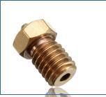

Left: Nozzle with over size throat and/or large chamfer as on left make extra work for extruder, and the power available already appears marginal. Select nozzles with minimum chamfer, just sufficient to avoid catching filament, as on right.
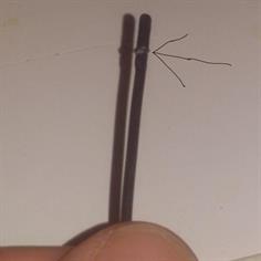
Left: This photo extracted from Geetech forum shows others have also found an identical problem with oversize nozzle throat, over generous chamfer, and short PTFE insert. My nozzle also had an over-size chamfer on entry throat. The nozzle chamfer chamfer should only be large enough to stop the filament grabbing as it is fed through. https://www.geeetech.com/forum/viewtopic.php?f=19&t=17097&start=100
And another:-
“The extruder was a whole different issue. Besides not being screwed in properly, the nozzle’s ptfe tube was cut wrong which left a gap before the nozzle. This caused a jam straight out of the gate”
https://www.polymatic.media/2017/07/23/geeetech-prusa-i3-pro-b-reviewed/
And another:-
“The extruder was a whole different issue. Besides not being screwed in properly, the nozzle’s ptfe tube was cut wrong which left a gap before the nozzle. This caused a jam straight out of the gate”
https://www.polymatic.media/2017/07/23/geeetech-prusa-i3-pro-b-reviewed/
A bigger problem:-
After replacing the nozzle and PTFE insert, the next “major” was regular filament feed stalls, and was very hard to find. The bearing in the pressure (idler) roller was defective. The faulty ball set (new!) ocassionally jammed and failed to rotate. The bearing center was ‘wobbly’ and turned very roughly. A throw-away!
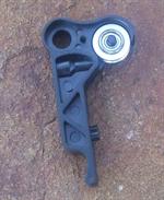
Worse, when reassembling, the release lever cracked. It is not a solid moulding, and badly designed as far as distribution of stress is concerned. This Geeetech Mk8 “plastic lever” extruder’s design and quality bring undone an effort to produce a quality kit!
With no alternative lever set, and not wishing to purchase another plastic type, I chose to convert to a Bowden setup. Rather than change to a V6 nozzle assy, I made a small adapter that ensured a quick conversion back to a full Mk8, as shown.
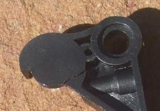
Left.Filament release lever is poorly designed, leaving opportunity for stress cracks.
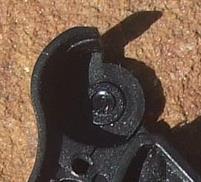
Right. My ball race was faulty from the start. Others have recorded locating pin breaks, leaving pressure roller jammed against frame.
Heat sink fins. Vertical or horizontal. Design or assembly problem?
This depends who you believe. (see blogs) Assembly of heat sink. Fins horizontal, not vertical. Extruders of both assembly methods are found.
And, big design flaw.
Actually the bigger problem than fin direction is the anodising on the heatsink, which is a highly insulating barrier. Must be removed with care to retain a flat surface, and a heat transfer compound used when re-assembling.
When my extruder broke, I came up with a quick, very satisfactory conversion.
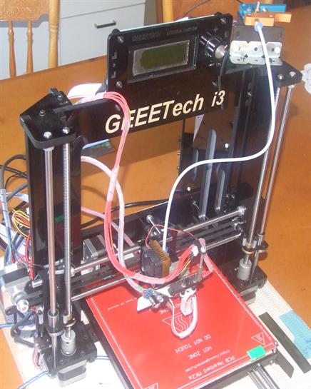
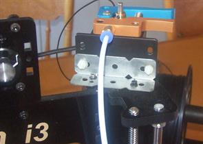
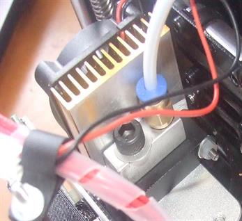
The quick change Bowden adapter is mounted to an existing 6mm tapped hole in heat sink.This modification leaves original nozzle and heater and mount in place.
The direct extruder drive was abandoned after problems with the pressure roller and cracked release lever. None of the available replacements were an exact match, and because of the poor quality of the arm, it was decided to go Bowden. The reduction of reciprocating weight on the ‘X’ carriage was a bonus, and no problems were encountered.
Conversion to a Bowden drive without major mods allows a quick return to fixed drive in under one minute (If your original drive is working!)
You must calibrate feed of the new extruder, keep the old setting handy if you wish to revert back.
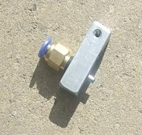
A small piece of 10mm square aluminium was cut, drilled, and tapped to form the adapter block. In the absence of a suitable scrap of aluminium, make the block from MDF, giving it strength with a heavy painting with slightly water thinned PVA glue. My prototype was MDF and was quite satisfactory, but don’t tp it until PVA has hardened. The adapter block mounts to existing holes with a short 6mm hex head.
To avoid gap, the bowden tube holder has a small stainless steel tube insert cut from a portable radio extension antenna. It is cut to an exact length to fill what would have become an ‘expansion chamber’ at the base of the tube holder, and so guarantee smooth feed of filament. The length of this small bit of tube will vary according to how far the throat tube is screwed into the mount block, and may need adjusting if nozzle assy is disturbed.
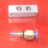
Left.The bowden tube holder has a small stainless steel tube insert cut from a 2.7mm section of a portable radio extension antenna.
Mount block is aluminium, but a PVA strengthened MDF proto was satisfactory.
Right. Assembled bowden tube mount, with guide tube, ready to bolt in place. Extension tube is cut to remove any gap where filament may move sideways. (Hole on side is artifact of my piece of scrap aluminium, no part of project)
BLTouch setup fun.
Two DIFFERENT coordinate systems, found on different Marlin i3 clone ”configuration.h” builds make setting up a BLTOUCH a GEEETECH i3 ProB GD2560A+ a trap for those adapting other user’s configuration files. You will have endless grief if you fail to understand the coordinate system used by original file’s author, and apply correctly to your machine.
Illustrating here with measurements as on my GEEETECH i3 Acrylic Pro B, GT2560A+.
Method 1. At home stop position, nozzle is considered at (0,0), making bottom left corner of build area, on my GEETECH i3 PRO B, (10, -6)
The four corners of the 200x200 white lined build area are shown as A, B, C, D.
At home stop, nozzle (red dot) is 10mm to left of build area (white square). It is also already, unfortunately, 6mm into build area in Y direction. In other words, the closest end of the build area already has a -6 Y offset, and leaves that 6mm unreachable because we are already on the stop!
The 3Dtouch probe (yellow dot) sits 47mm in front of nozzle, and 13mm to right.
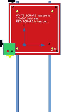
Under this system, these next will be coordinates of white square build area.
Nozzle here sits on home stops, (0,0).
POINT A. (10,-6) Build area lower left.
Unobtainable! As we are on Y stop, we will NEVER be able to lay filament in that ‘lost’ 6mm.!
Point B. (210,-6) Build area lower right. Likewise!
Point C. (10,194) Build area, upper left.
Point D. (210,194) Build area, upper right.
(Yellow dots on build plate are artifacts from an article where I show the impossibility of obtaining a probe square 20mm in from build area edges with an “out front” BLTouch mount.)
So, in my Geeetech i3 ‘configuration.h’ :-
// The size of the print bed
#define X_BED_SIZE 210 // -(-10) + 200 = 210
#define Y_BED_SIZE 194 // 200 – 6=194
Note how the nozzle sits on my GEEETECH i3 Pro B Acrylic, already using some Y!
There is no Y_MAX
end-switch, and so if software limits are not set correctly, bed may slam end when probing.
end-switch, and so if software limits are not set correctly, bed may slam end when probing.
Nozzle at (0,0)
Method 2. Build (print) area lower left corner is considered (0,0), so home on my Geeetech i3 becomes (-10,6)
This system suits perfectly where stops can be set so nozzle sits at lower left corner, and makes all work with setup and Repetier easy, but requires a little thought in setting up for probe, and print software.
You may use any method you choose, but must understand it fully. Blindly copying someone else's 'configuration.h' file will cause you grief.
What's This?
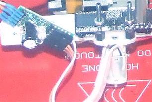
What’s this, attached to probe!
First, not knowing what decoupling existed within the BLTouch module, I added 100uF across the supply to avoid any chances of switching pulses causing other problems.
Second, during installation, I needed to know the fast pulse was occuring.
A LED placed series with a 1000 ohm resistor across the output gives a quick flash, indicating all is working and is not such a load
as to degrade the output. Truth is, it was easer to leave in place than remove it!
The easy to install ‘out front’ BLTouch mount gives a skewed and limited probe area. I suggest looking on Thingiverse for a probe mounted closer to the nozzle.
Suggestions for GEEETECH.
Your suppliers are wrecking your reputation. Bent chrome rods, and so rough as to catch the fingernail like gritty sandpaper. An extruder with unacceptable design weakness’, assembly errors, and component tolerances.
Your manual still has errors flagged years ago. Get it fixed!
Pre calibrated stepper drivers, especially for the Z axis would save endless struggles with missing ‘Z’ steps
Dispense with four bulldog clips. Replace with low profile metal ones.
An upgraded power supply would not be that much more expensive.
Offer a model with integrated BLTouch. The extra cost would save your builders save endless hours.
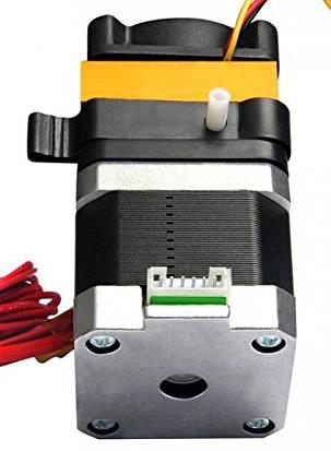

Give the plastic lever version a miss!